


Exothermic welding, also known as aluminothermic welding, is a chemical process which creates a permanent molecular bonding of two or more conductors. As a result of this fusion, the connection is more reliable and durable than the mechanical union, and its conductivity is equal to or greater than the metals it connects.
Where is it used?
The exothermic welding is used in earthing systems to ensure the safety of joints between conductors.
Advantages of using Apliweld® Secure+ for exothermic welding
– Increased safety thanks to remote electronic ignition (Bluetooth)
– Use of non-flammable material for ignition
– Reduction of logistical costs
– Reduction of errors
– Reduction of setup times
– Increased process efficiency (even in wind or rainy conditions)
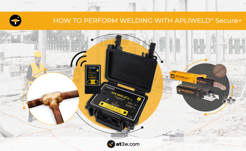
How is an Apliweld® Secure+ exothermic weld with an electronic ignition carried out?
Thanks to the innovation efforts of Aplicaciones Tecnológicas, the Apliweld® system has replaced the traditional powder with a unique tablet format compound.
Perform exothermic welding with electronic ignition by following these steps:
Clean and remove any debris from the conductors and the mould
In a exothermic welding it is very important that the conductors are clean and dry, to avoid unacceptable welds and hazardous reactions (with material leakage) when the molten weld material comes into contact with dirty or wet material.
Clean the conductors to be welded with the AT-061N brush.
*We recommend that you see the particular cleaning specifications of each type of conductor and/or compound to be removed in the following link.
Open the clamp and place the lower part of the multiple mould required.
In the MM-CTX case (X is the diameter of the tool) you will find the multiple mould clamp (MM-053N) with the hopper and the MM-PH lower part mounted. If you want to weld the tool, the lower part must be replaced by the split part in the case:
- MM-PH: part for horizontal welding (T conductors, cross, linear,…). Is placed to make welds between cables. By turning it over, it can be used to weld tapes.
- MM-PTX: lower part for vertical earth rod welding (usually T). The part has the required earth rod diameter (MM-PT14, MM-PT16….) and is valid only for that diameter. See machining diameters for earth rods at point C2.
For vertical welding with an earth rod, fix the support clamp (AT-082N) about 4 cm from the end of the earth rod to be welded. Open the lower part of the MM-053N pliers and place the split piece.
Place the clamp on the support pliers and insert the earth rod into the channel of its diameter. Close the lower base to correctly clamp the mould to the earth rod and thus prevent material leakage between the graphite split piece.
At this point, the clamp should rest firmly on the support pliers, so that you have both hands free and can comfortably position the remaining conductors afterwards.
Heat both pieces of graphite
Before making the first of a series of welds, heat the two pieces of graphite with a torch to 120°C for an acceptable first weld and for the safety of the user.
The main cause of material splashes and porous welds is moisture in the mould. Graphite absorbs moisture at room temperature, so it needs to be heated above the boiling point of water to remove it completely.
Place the lower sealant, the conductors and the other corresponding sealants
Place the bottom sealant centred over the base of the mould. Then place the conductor(s) to be welded, depending on the type of joint you wish to make, making sure they are centred on the mould part. Place one or two sealants over these:
- For T- or linear welds, simply close the mould by operating the lever and pressing as hard as possible to prevent material leakage.
- For cross-welding (i.e. for connections in a different plane), the previous step is repeated by placing a new conductor on the last sealant, and on this, one or two sealants depending on the conductors, so that in all cases each conductor is always between chamber sealants.
Once the mould is closed, place the metal disc (10 come in each electronic starter box) and then the tablets. The number of tablets according to the connection to be made is also defined in our manual, click here to learn more.
Open the ignition unit and connect the connection clips
Connect the two pairs of pins to the ignition unit (it does not matter how the pins are connected to the device, as the detonator cap has no polarity).
Insert the plug at the other end of the cable into the side connector of the mould and connect the clamp to the upper contact of the electronic starter. It is very important to ensure good electrical contact between the clip and the filament, so that the clip does not come into contact with any other area of the cap.
The APLIWELD-E Kit (AT-100N) includes 5 spare clamps so that the connection clamp can be replaced when it is worn or damaged.
Step away from the mould and turn on the ignition
Move away from the mould at the maximum distance offered by the connection cable (2 m).
Turn on the device by pressing the “On/Off” button. You will hear a sound to indicate that the device is running and you will notice that the indicator light is green.
For greater safety, the process can be activated by Bluetooth: turn on the remote control and wait for the blue light on the equipment to stop flashing, thus indicating that the Bluetooth is connected.
Press both ignition buttons at the same time to start the weld process
Press the two ignition buttons (either on the unit or on the remote control) simultaneously, keeping them pressed until the reaction starts. When the buttons are pressed at the same time, the in-process light will come on and you will hear two beeps of approximately 3 seconds duration and then a continuous tone. During this last tone the welding will take place. Press until the process starts.
If the reaction does not occur or if you do not hear the sound signal, please consult our manual.
After the reaction, wait during 15 seconds and open the mould.
Once the reaction is over, wait 15 seconds before opening, assuring the melting of the materials.
Open the mould cover using the appropriate handle clamps and safety gloves, since the whole system is very hot. Exercise extreme caution.
Take the welded conductors out of the mould
Cleaning the mould
Use the right cleaning tools to remove the slag and clean the crucible. AT-064N is the 14 appropriate brush to clean the welding cavity. Use AT-062N brush to clean the mould cover, specially the Electronic Starter cavity.
Find a detailed description of cleaning tools and how to use them on section C3 in this manual.
Once cleaned, the mould is ready for a new welding. No heating step is required if the new process is carried out within 10-15 minutes.
All the cleaning accessories described in these instructions are included in the AT-069N Accessory Set, click here to learn more.
Also, if you are an engineer or technical professional related to the industry and want to discover first-hand what solutions are offered by Aplicaciones Tecnológicas, we invite you to attend our free online courses hosted by industry leading experts. Access now to our calendar for the next webinars by clicking here.